
This is the story of a little robot named Antonito which evolved over the course of 18 months by Ti Zhao, Jeremy Kimmel, Paul Long and myself while working at Social Construct. Here's it doing its job at a SoCo apartment building in Oakland, CA:
This post tries to capture the evolution of the robot detailing what worked and what did not (in both hardware and software). When we started working on this we quickly realised that there are very few people making production robots from scratch and the entire process is shrouded in mystery. I hope to demystify robot creation, sensor choice and robotics software for someone thinking of doing the same. This blog does not go into specific code or detailed hardware schematics (I can do that as a followup if there is interest) but is designed to be more of a casual read.
What exactly does it do?
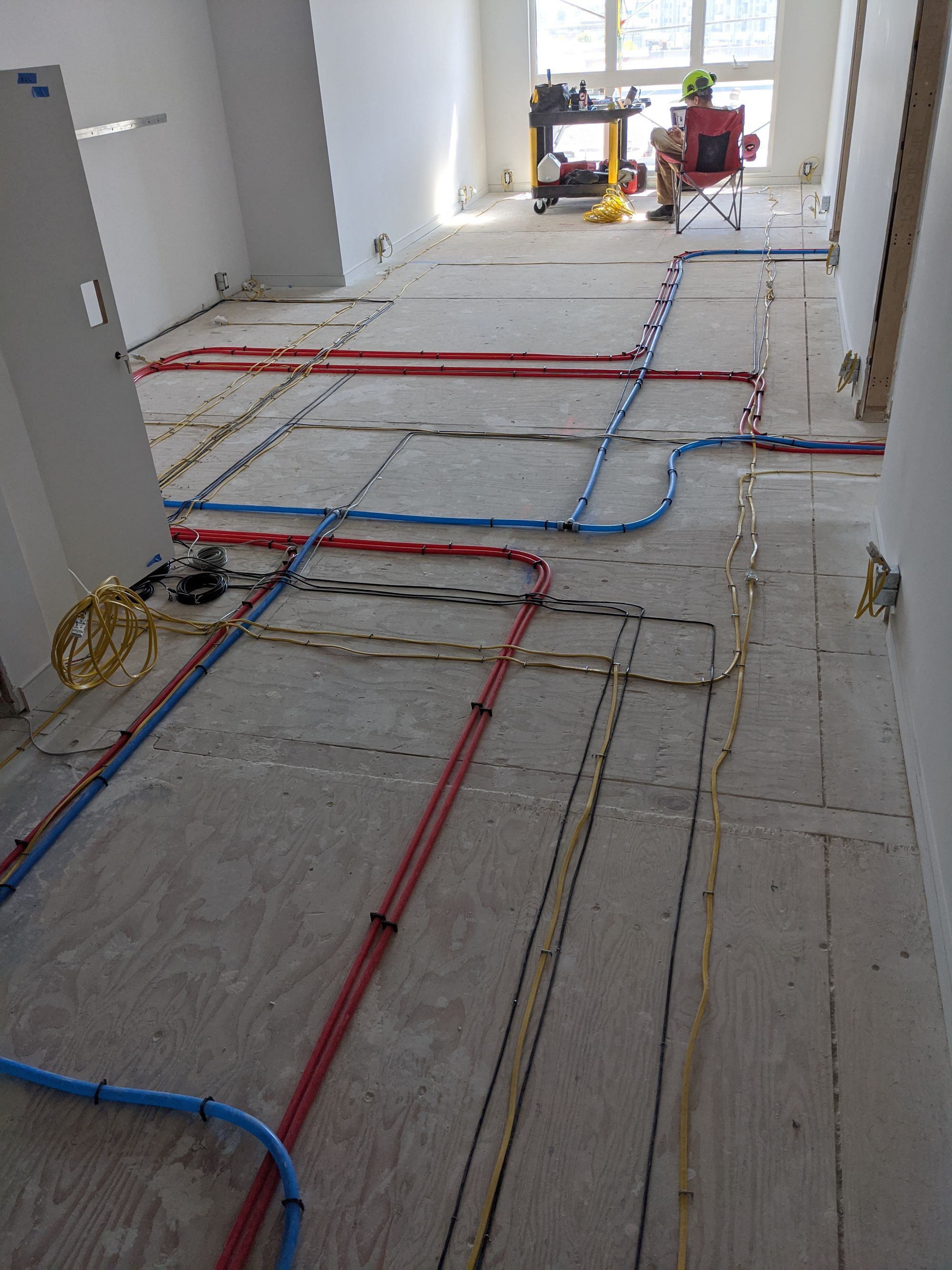
Social Construct utilizes a brand new method of quickly finishing apartments by utilizing a raised floor. This allows the shell / structure of the building to be built up quickly without any apartment specific piping, electrical or data connectivity. The electrical and plumbing is underneath your floors and it looks like this:
A floor is then laid out over these lines:

The floor is prefabricated and so are the 'pucks' that hold it above the subfloor. This allows super fast installation of the plumbing + electrical lines + floors as long as the lines don't interfere with the pucks. Since the lines are laid down before the floor pucks its imperative that they are laid down accurately. The install crews would look for marked channels in the floor to aid them with the install which would look like this:
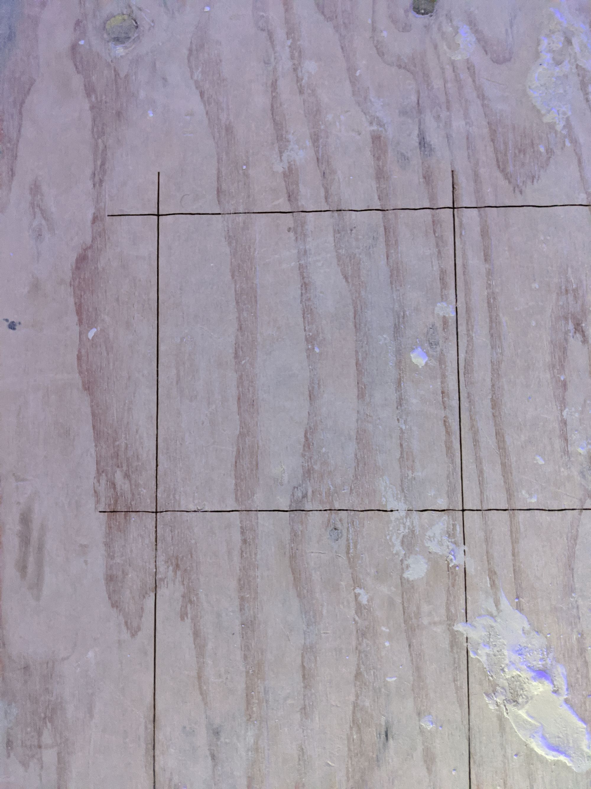
The max allowable error or tolerance on these "channels" is ~1.0 inch. While this doesn't sound like THAT precise, trying to maintain 1" over a distance of say 40ft turns out to be extremely difficult for robots AND humans.
These channels are devised by the mechanical/construction team and marked on CAD. These channels were originally being marked on site by a team of 2 people who would measure distances from a closest wall or another channel, consult CAD and lay down channels using two chalk lines. This whole process would have to be repeated 30-40 times depending on the size of the apartment. It's hard to humanly keep referencing a far away wall so channels would be drawn in reference to other channels and accumulated errors could quickly blow through the tolerance.
Enter the robot
We realized that this sounded like a job for a robot. The first problem was localizing the robot with 10mm of accuracy. We chose 10mm as it left some tolerance for real world randomness and also the fact that this allows some tolerance in matching up the CAD to the real world (construction isn't very exact).
The VR days
The first idea was to use SteamVR. Having experienced VR we were confident that the HTC Vive lighthouses and a HTC Tracker would be able to do well.
The prequel: Antonio
The first prototype put together was made using the roomba create2 robot equipped with a HTC VR Tracker and localized using lighthouses. You need to use the SteamVR SDK on windows to read the tracker and localize it. This seemed to mostly be quite accurate. Sensor output variance was < 10mm when still and HTC seemed to have solved robotic localization for mankind. There was much rejoicing. We nicknamed this one Antonio.
Seemed like the only problem was now with the roomba create2 platform. The roomba is a differential drive robot (uses two separate DC motors) whose speeds you control directly through a serial interface.
It wasn't easy at all making the robot go straight or turn very accurately, specially from a stop. We quickly realized this is just a universal problem with DC motors and diff drives in general as they aren't meant to be superbly accurate with RPM, specially at startup and under load. Coupled with the fact that VR itself had noise, we decided that a more accurate drive system was needed before we invested more time into the robot.
The option was to assume motors as inaccurate and tap into the motor encoder to get odometry OR simplify our lives by using a stepper motor. My previous experience playing around with holonomic drives forced me into thinking that since only straight and perpendiculars lines are needed - maybe a tri- stepper motor setup with omni-wheels is the best approach? Initial tests were promising!
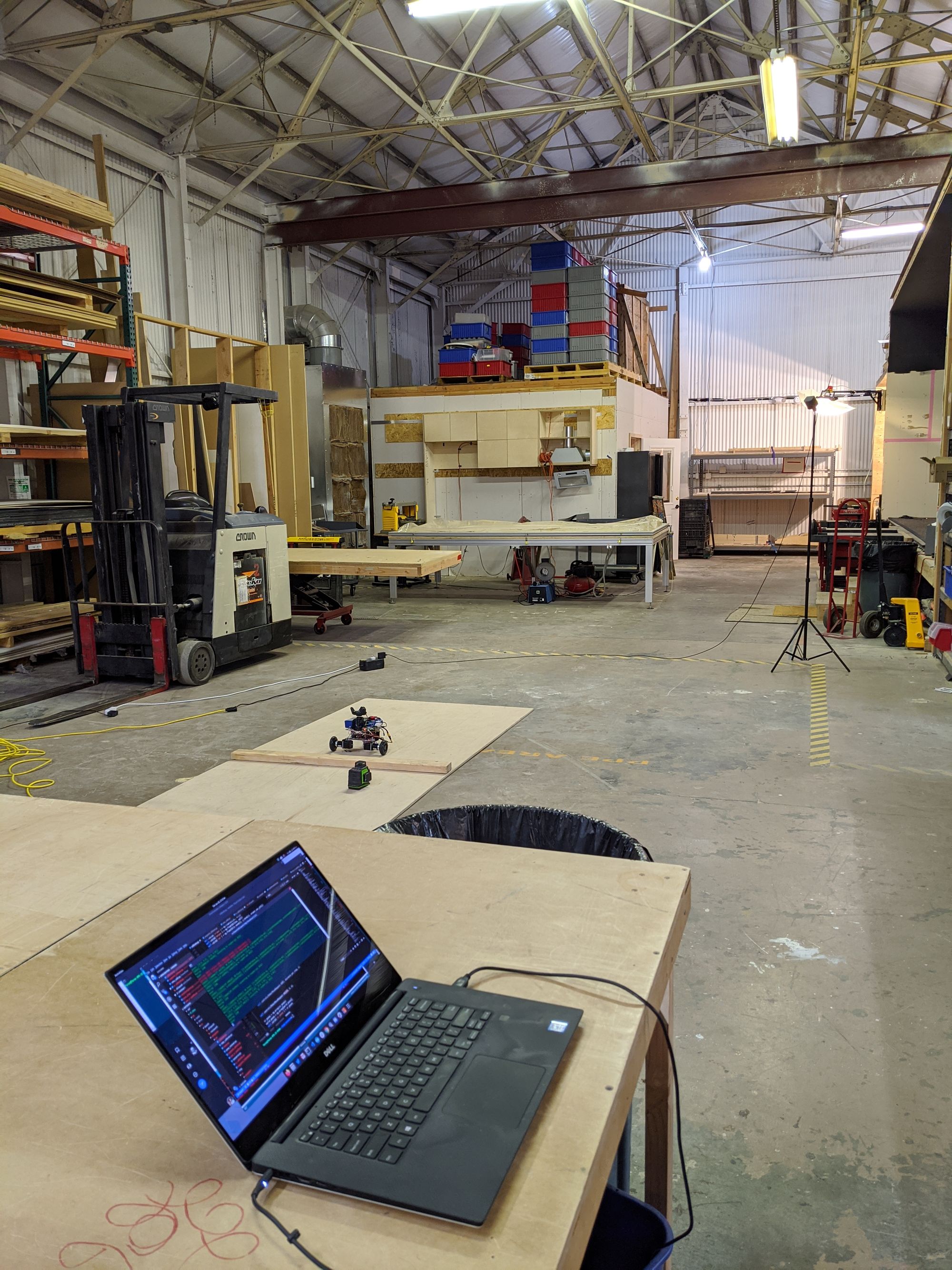
Antonito the robot
I was able to get a tri-motor plate from robotshop (they are awesome!) along with some nema-17 motors and plates so that I don't have to do any fabrication. They also have a decent selection of omni wheels and adapters to choose from! Add a DRV8825 stepper motor driver from pololu.com (another awesome resource), an arduino and a 3 cell turnigy LIPO battery from hobbyking (great for batteries!) we have this:
The arduino comes with a nice library to drive the DRV8825 and it was pretty simplistic to hook up. You DO have to calibrate the current for the motors before you energize them (or risk the deadly magic blue smoke of death!) but thats a topic for another blog post.
From there it was pretty easy to slap on a HTC VR tracker on this guy, add a raspberry pi 4 and a servo motor to lower or raise the marking sharpie that we were using:
Much thanks to Paul at SC for 3d-printing that servo compatible sharpie up-down mechanism you see.
At nearly 1/3rd the size of the create2 and weighing much less, we started calling it Antonito. The name stuck and antonito was born!
What about the software?
At this stage the RPI 4 is running ROS1 along with libsurvive. These smart folks have reverse engineered the raw USB data stream from the HTC tracker and run a PnP pose tracking and lighthouse auto-calibration system (!!!) which basically lets us bypass steamVR (which is only available on windows) and run all this locally on a RPI4. Initially we were running SteamVR on a windows laptop and connecting to the HTC Tracker via a bluetooth dongle. Bluetooth was wonky if the laptop was more than 10 feet away from the tracker and that forced us to find a more direct route. Luckily with libsurvive we could read HTC Tracker data very fast over USB and also provide power.
The RPI4 connects to the arduino over serial and the arduino understands step commands. You can also issue it commands to rotate and move forward. Odometry is calculated by the arudino using the omni 3wd robot kinematics available in very simple form here.
The kinematics are sent back over serial to the RPI. The RPI has a simple kalman filter with state x,y,𝜃 which uses the odometry as the motion model to predict the future state then update with real world info from VR. Extensive hand fine tuning of the process and update variances was involved. It seemed to work very well, atleast most of the time.
Laser upgrade
The sharpie, as you would imagine, started to show problems with real world usage. The pen would gum up with saw dust and the pens would just dry out with exposure. We tried many variations of 'pen' like devices like crayons, roller pens, pencils, chalk but nothing would survive an extended test reliably.
The winning idea came almost randomly one day while discussing the problem with Ben Huh (the founder) who had the ingenious recommendation of using a engraving laser! Since our subfloors are all wood - this was an excellent idea. Lasers also have no moving parts, are easily turned on or off and surprisingly don't need much power. We were able to order some 2.5W lasers from amazon (which ofcourse arrived instantly - what an age!) and we had this working in 2 days:
The laser is controlled through RPI's GPIO.
Friendship over with omni wheels
While the omni wheels looked cool and seemed to work well we realized that it was extremely difficult in practice to make the robot 'holonomic' (move freely in all directions). For example to move the above robot vertically at 200rpm the following needs to happen:
Motor 1 speed: 0 rpm, M2 speed: -200rpm, M3 speed: 200rpm
Such are the kinematics of the tri-wheel setup. While this seems simple, moving it horizontally is a bit weird:
Motor 1 speed: -400rpm, M2 speed: 200rpm, m3 speed: 200rpm
Controlling motor speeds (even a stepper) is not exactly easy to do precisely - the only way is through microstepping in hardware. Microstepping is usually done in powers of 2 so valid microsteps are 1/2, 1/4, 1/8, 1/16 and 1/32. However microstepping comes with some fineprint: you also lose roughly the same amount of torque. Since we needed to carry a heavy battery this was out of the question and we were restricted to a software only solution.
Further the steppers are fighting each other in this setup, this meant it was more likely to stall and skip under the load of a 10lb battery. It also meant it was more like to skip if it hit a imperfection in the surface.
Basically in the end we were limited to using vertical motion and rotation which were the only two motions that worked reliably. Horizontal would cause skips and small changes in orientation - motion that wasn't vertical or horizontal required speeds of the motor which were not exactly nice multiples - making controlling it through a microcontroller extremely painful.
In real world experiments it also became obvious that the omnis are unable to climb over even the smallest objects well. Sawdust and dirt started gumming up their tiny rubber rollers. We needed some big rubber wheels.
Diff drive is my best friend
So out the omnis went, and we went to a traditional diff drive setup using some big rubber scooter wheels (80mm) from pololu. Moved the brackets to right angles, added a castor wheel up front and installed the big fat battery (BFB):
The nema17 motors got an upgrade with a 100:1 gearbox for near infinite torque. Though this seemed like overkill at the time it would work out very well for use since it lets antonito climb over screws, small tools or pretty much anything half the wheel height.
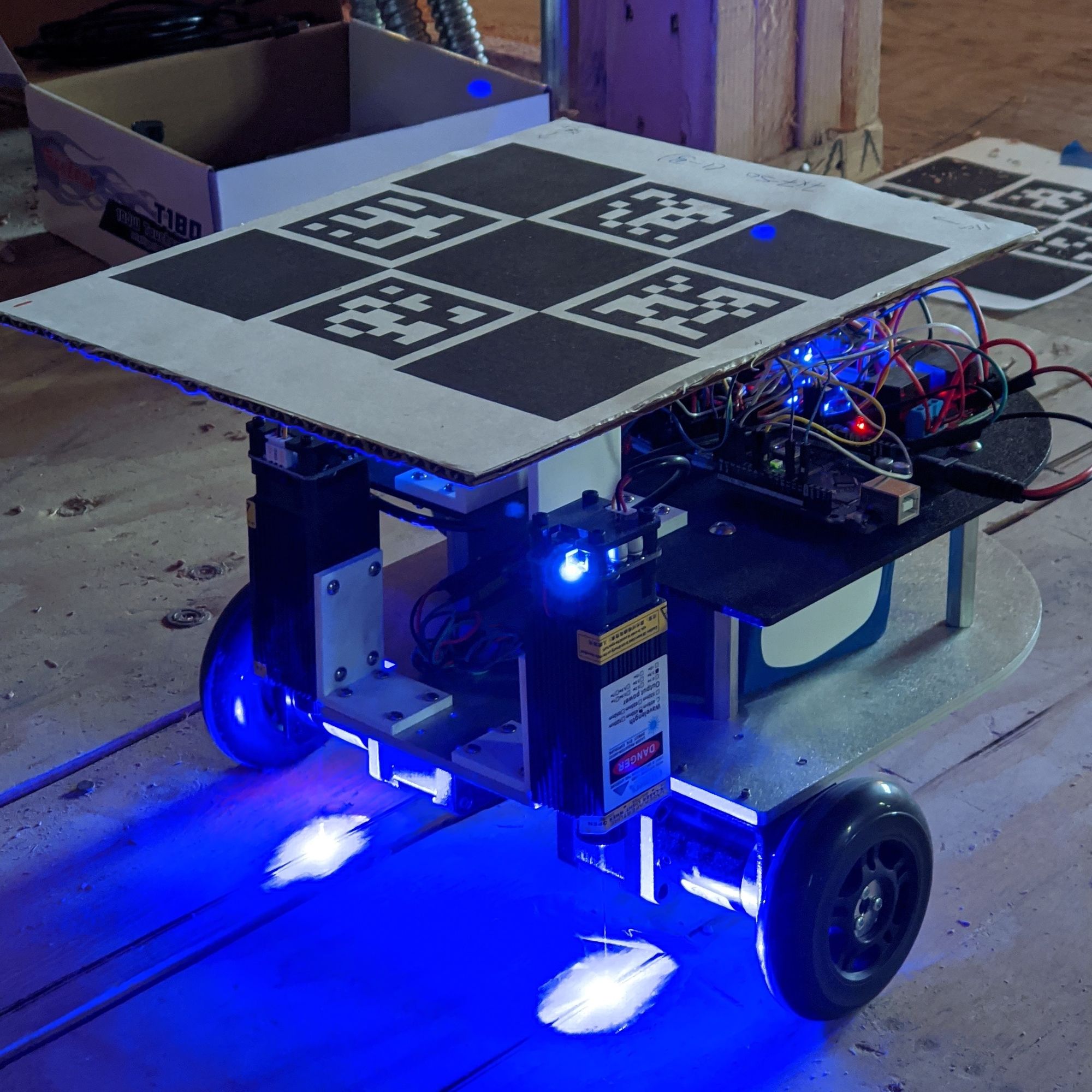
Productionizing Antonito: V2
It was time to make a real stable chassis for antonito which can safely house a battery and where we knew distances between items accurately. For example its important to know where the center of the VR tracker is relative to the driveline of the robot, otherwise fusing the odometry with VR position is going to be extremely weird. We also need to know exactly where the lasers are in relation to our robot origin. We also need this robot to be strong enough to hold a 10lb 1200wh battery and not fall apart or catch on fire due to flimsy wiring!
With help from the amazing hardware team at Soco (shoutout to Jeremy Kimmel) we were able to put together a 3D model in solidworks of what we wanted:
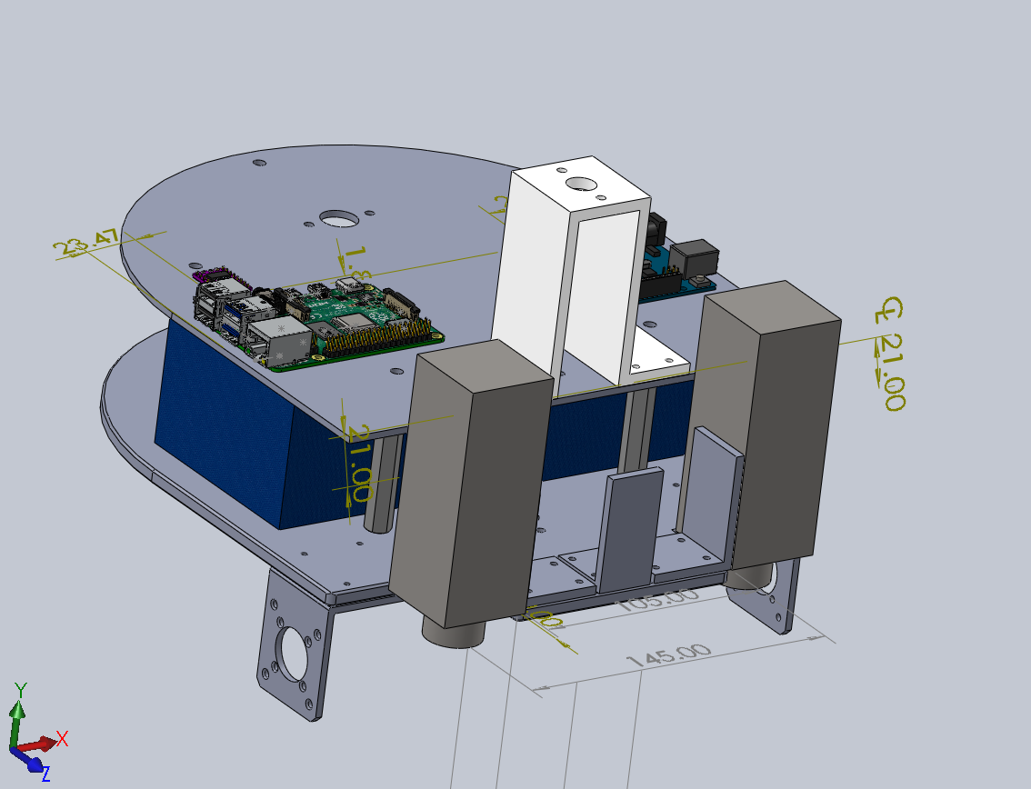
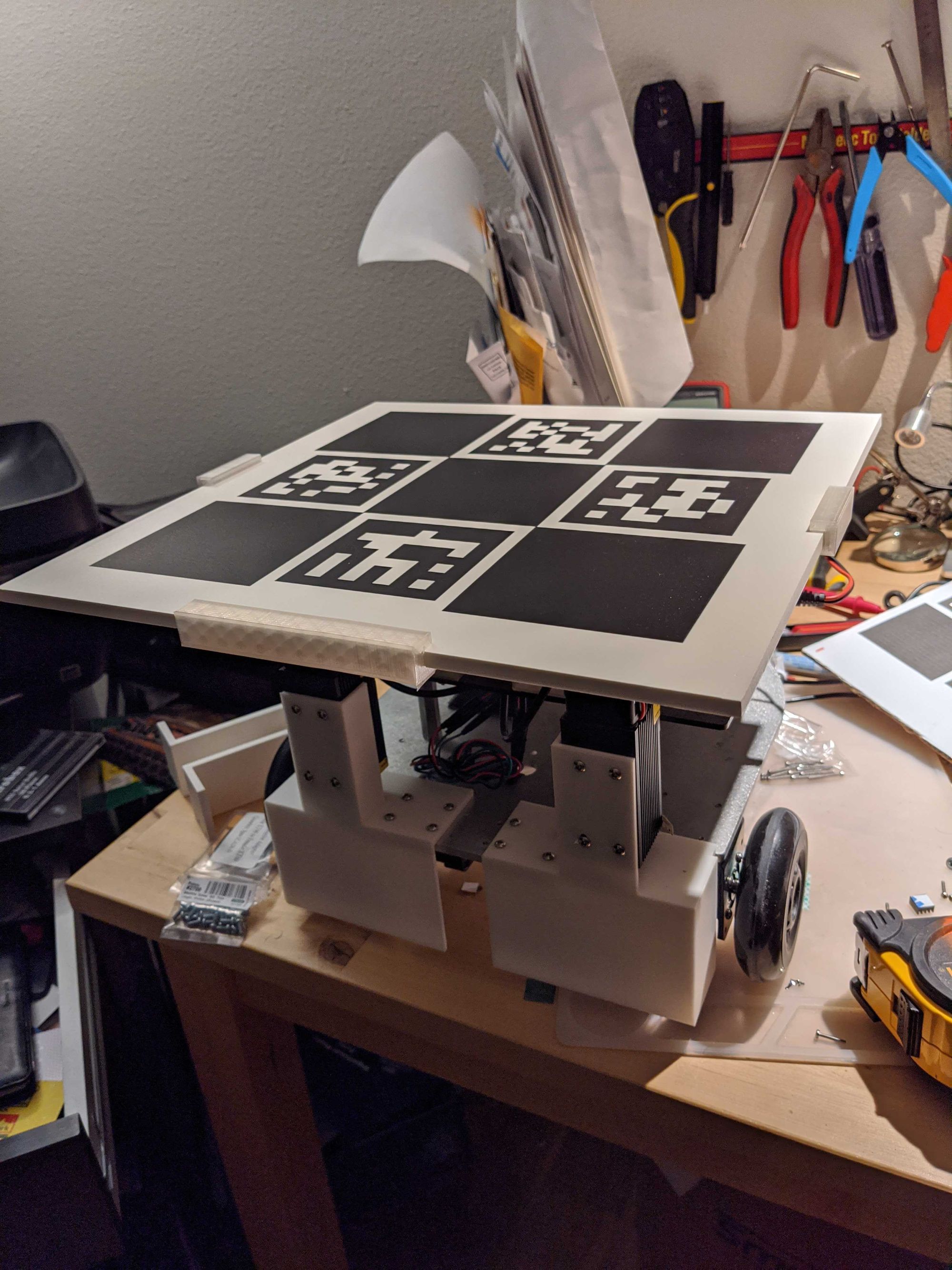
Details of exactly how we got to this point with solidworks is yet another blog post (which I can do if there is interest!). But that solidworks design above can get translated (pretty easily) by a friendly neighbourhood laser cutting workshop, a creality 3d printer and some manual labor to this:
We now had a super accurately well made robot, front wheel drive which makes rolling over stuff easier. Lasers close to the driveline center to reduce the effect of any errors or movements. Black ABS base for the tracker to prevent any weird reflections that throw the light sensors off. Dual mounted lasers which cut time in half. Safety shutoff relays cuz lasers.
Antonito was ready for prime time!
Real life testing
We tested the robot in varied situations for over a month. Our production sites were going to have rooms which were about 40' x 20' in size. We quickly figured out that the absolute max the HTC lighthouses could reliably do was 15' x 15' without the tracker losing sight of a lighthouse. This was suboptimal but workable - if we could reliably calibrate the VR to multiple points in the room the different areas would overlap perfectly and all would be well.
Estimating the robot location
It became quickly clear that noise in our VR output was pretty far from being systemic (or gaussian). VR errors are extremely sporadic and sometimes way out of whack. The best results were obtained using a generic particle filter:
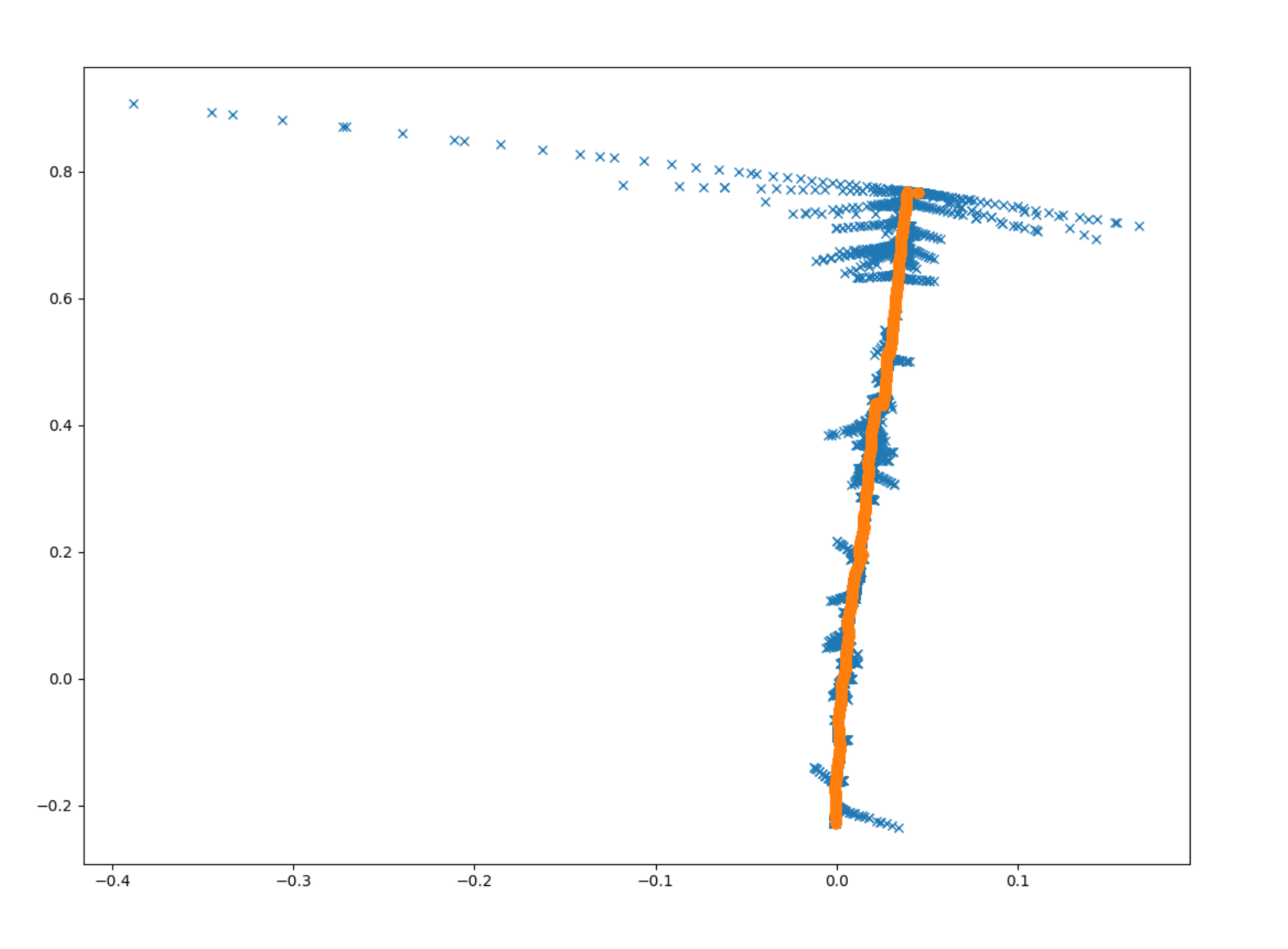
Blue is the actual data point and orange is the filter's approximation of location.
Initially we were using a Kalman filter. This failed badly due to the sporadic (and non-gaussian) nature of the error in the VR sensor.
You can watch how well the filter localized the robot live in the video below. Green circle = mean / robot position estimate, blue = particles, red = VR measurement
Even with all this we were only able to get VR to work reliably in near perfect environments. This usually included:
- NO reflective surfaces. The robot itself had to be covered with paper
- NO sunlight (even indirect)
- Lighthouses at 90 degrees to each other (not diagonally across). This would mean there would be a big shadow area in the corners which was a bummer.
- Restrict play area to 10' x 10'
Even with all this we would randomly get sporadic errors. We also realized that:
- Orientation error was quite large and extremely sporadic depending on the position of the tracker. std dev > 0.2 rad was possible in some places which is very bad.
- the VR plane is supposed to be flat wrt to gravity - however it didn't exactly seem this way in real life. There seemed to be sort of an angle relative to ground which would become more and more obvious on the edges of the play area. This was also observed by the folks at NASA
- Dust and debris would cover the lighthouses and light sensors on the tracker and cause errors to grow to very large values.
- Vibration from the motors would cause havoc with the built in IMU in the tracker and cause extreme drift. We had to turn the IMU off.
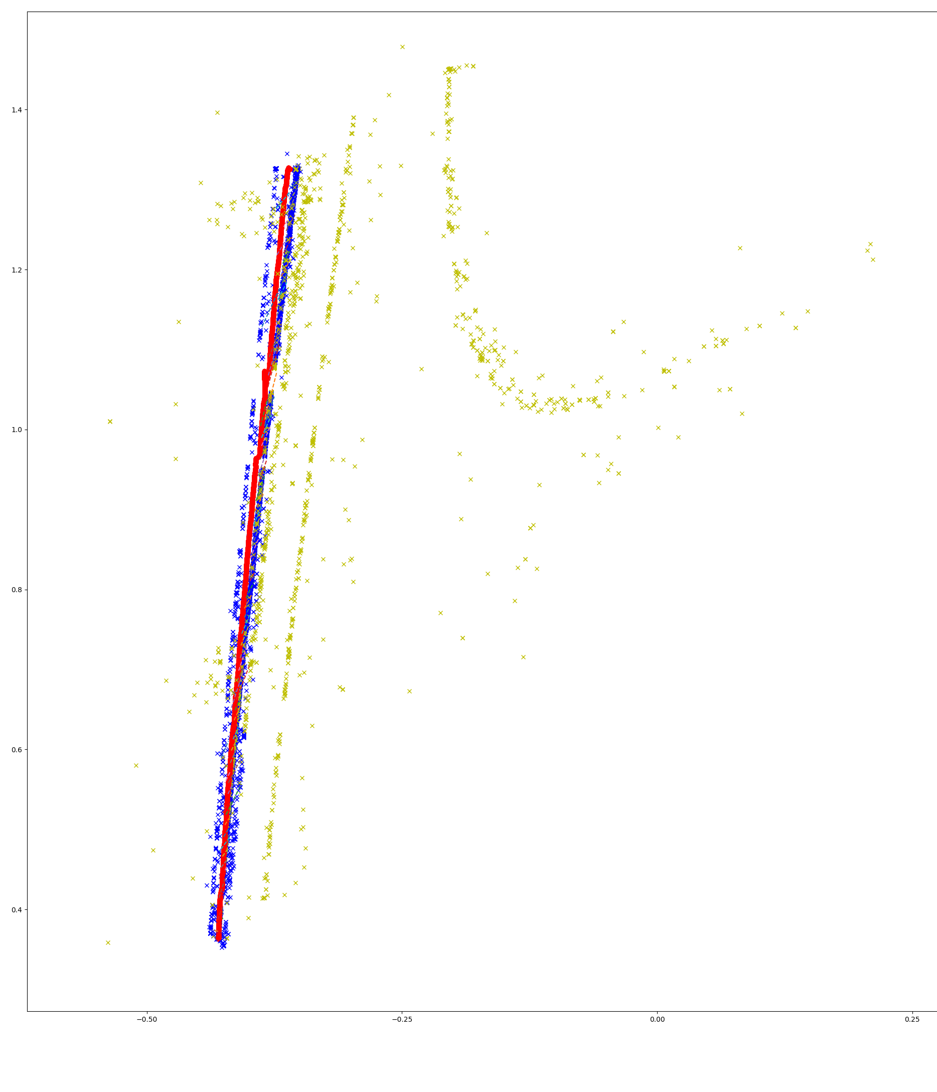
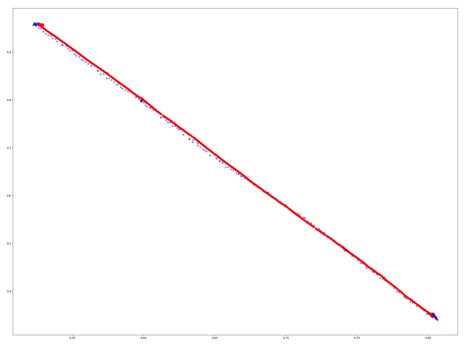
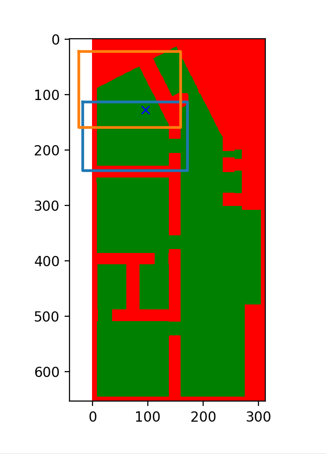
We tuned and tuned - but in the end it felt like we were tuning our particle filter to the situation. We had to add some clever outlier detection back (basically drop the measurement if too far from all the particles). The end results looked like this:
- blue: measurements deemed good
- yellow: measurements deemed bad
- red: robot position estimate
While this worked, confidence was rapidly eroding with this setup. Nothing makes you doubt your localization solution more than unpredictable errors. Filters can only do so much. There had to be a better way.
Computer vision to the rescue
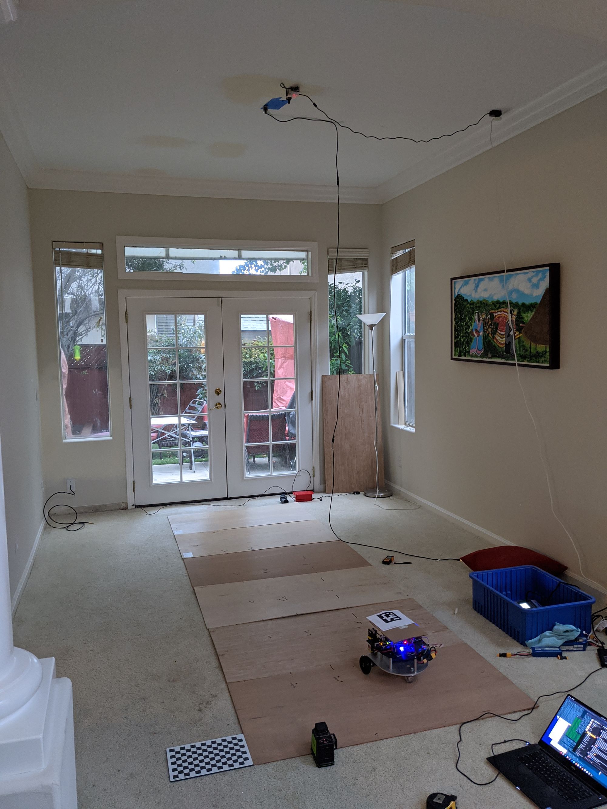
Covid19 was in full swing at this point in time and all robot development had been moved to my house. I had to clear out a nice area in the living room which became the lab:
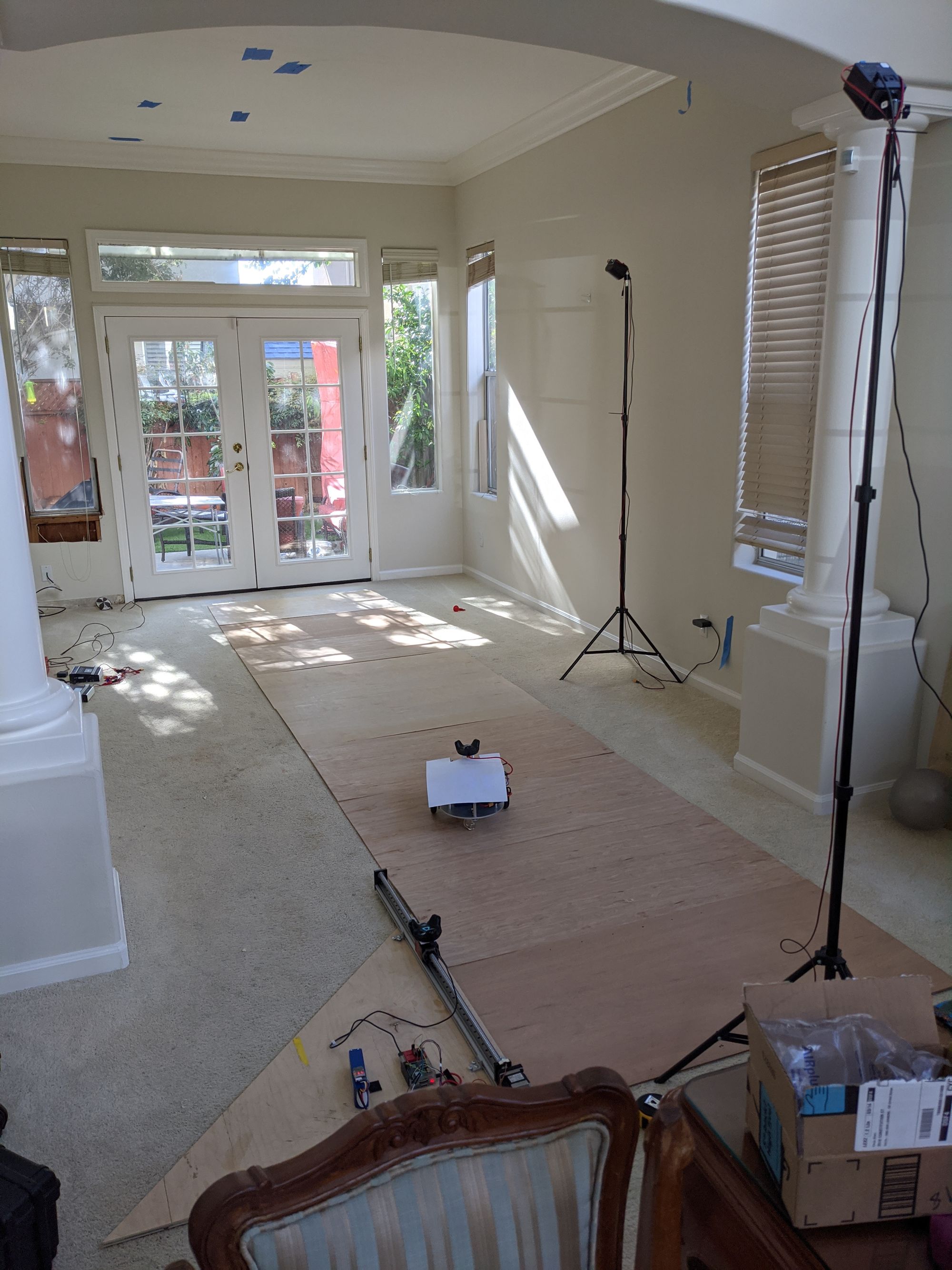
As anyone who works from home will realize - this basically meant I had a LOT OF TIME since I was basically at work day and night. This meant I could iterate crazy solutions - like switch the localization to vision based right before deployment. I threw together a quick hacked solution and results were extremely promising:
Those numbers are in cm's! This is using the 3d pose estimation which is built into the opencv aruco library. Without doing much I was able to get roughly 1.5cm accuracy and > 0.05 rad orientation accuracy. Also the results were stable (the std dev seemed super low)
I was able to quickly throw together a 'tracker module' which consisted of a RPI4 attached to a see3 USB 4k camera:
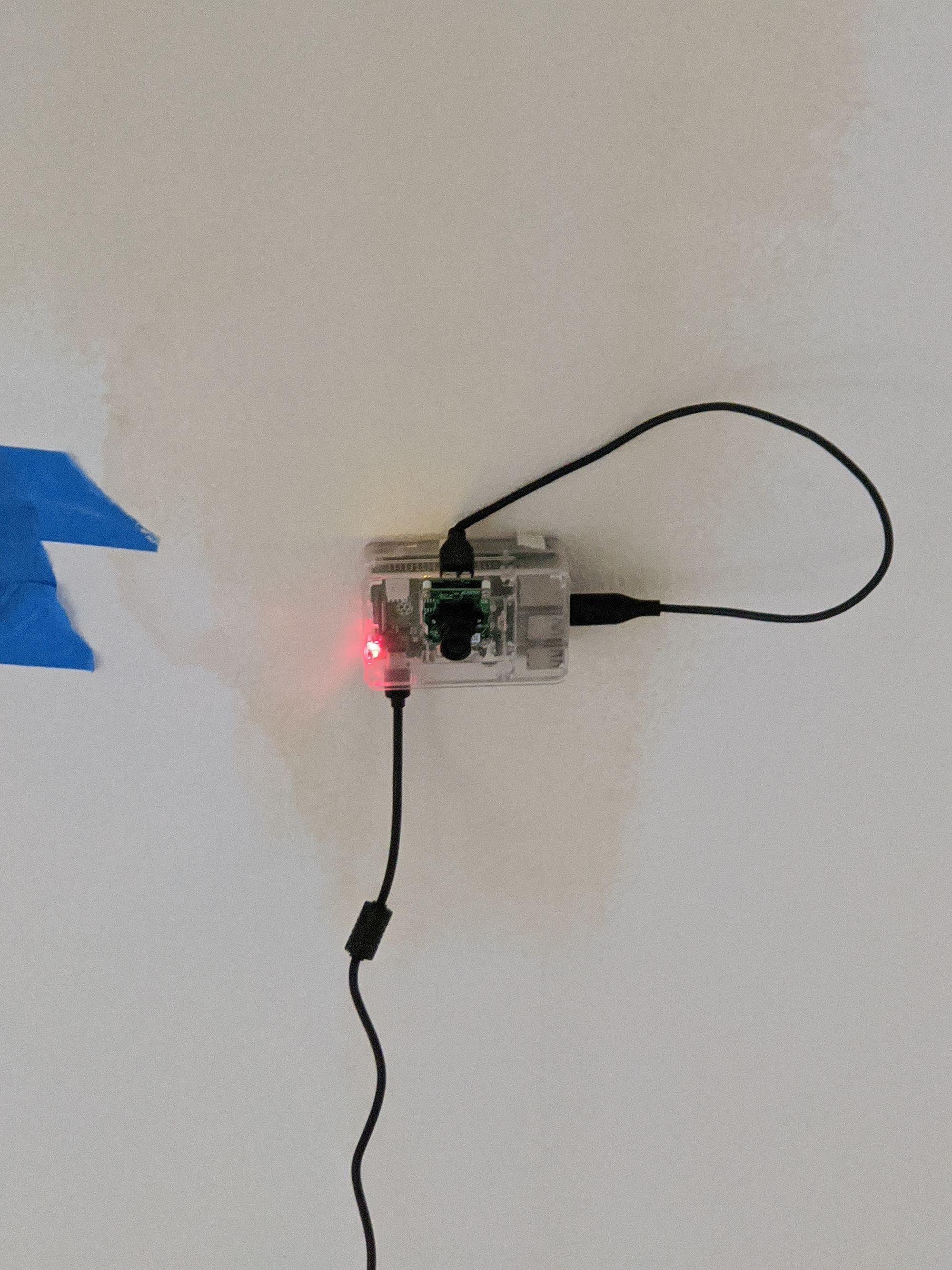
The checkerboard is used to provide an anchor for origin and zero heading. All results were measured from this for accuracy comparisons. The results were immediately shockingly good:
No outlier detection needed! Now this is what we call a sensor. Absolute deviation seemed to be < 15mm at all parts of the coverage area which was now 12x15ft!
From 3D to 2D
While the results were the best we've seen to date, they were still a bit jumpy - they seemed to be heavily effected by marker print quality and lighting. At this point we were using the estimateSinglePose function in the aruco library which does depth calculation using the camera's focal length and the size of the marker. Since our problem was contrained to a 2D plane this was doing too much. The simple solution was to confine the issue to 2D and 'calibrate' the image to the real world using 4 or more known points. Then we would be able to find the transform (rotation and translation) of our camera with respect to this image plane using a pretty routing computer vision solver (solvePNP):
Depending on how the calibration is done, each pixel on the image corresponds to some known distance. Once the R|T (Rotation / Translation) matrices have been calculated from above, using them to find real world position given image pixel location involves some not so complex computer vision equations.
The aruco library outputs 4 corners of each marker thats detected. The center is simply the mean of all these four points. Orientation is calculated simply by calculating the angle of all four lines that connect the 4 corners.
This gave us an extremely accurate and stable pose for the robot. I was able to get < 5mm absolute deviation on the entire image and an extremely low standard deviation even while in motion. Localization was indeed solved!
We later moved to a simplistic banner which we would lay out on the floor to calibrate the cameras. The more points the better.
Infrastructure
To keep things fast the computer vision tracker was written in C++ and ran natively on the RPI4. It uses v4l to poll the camera directly and does a single copy coversion from YUV->RGB.
In order get 5fps tracking on the RPI we have to do some smart stuff. Once we detect a robot we only scan in the adjacent area for the next frame (since the robot doesn't move that fast). So while a full 4k image scan takes 2s, a subsequent followup scan takes 150ms.
There's also a laptop that can listen on the same network and helps visualize the position of the robot and camera coverage areas.
Room scale tracking
We would stick our cameras to the ceiling knowing roughly that each can cover 12' x 15' in area. Thanks to our filter and UDP broadcasting, we didn't have to do much else except make sure the coverage areas overlap a little bit like this:
Antonito would move from one camera's field of view to the next. All cameras have been calibrated using the same coordinate system so they all report back global coordinates (distance in meters from a arbitrary origin). Once detected the position is broadcasted on UDP broadcast address for anyone to listen on. This way the robot can listen to multiple cameras and the particle filter just treats those as separate measurements, easily fusing multiple cameras and odometry to get a pretty reliable positional estimate.
Navigation
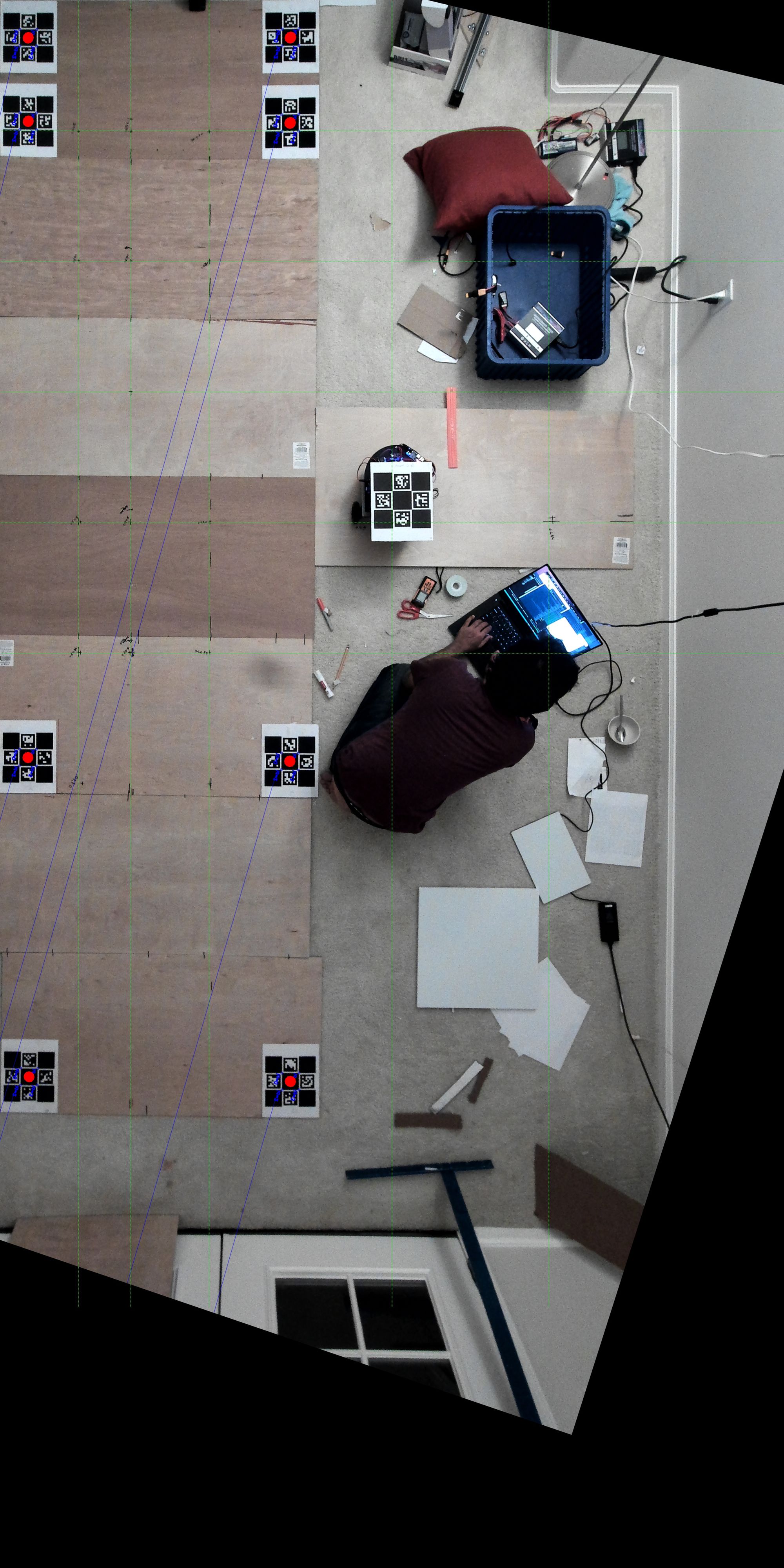
The laptop is also responsible for reading in CAD in dxf format and converting that to a occupancy grid / map which is used to do basic path planning using A*. Since multiple cameras (sometimes 7-8) could be required to cover an entire apartment our A* is smart enough to figure out where antonito has camera coverage and where it does not.
This meant the robot was able to go around known obstacles (walls, doors, uncovered camera areas) to get to its destination:
Battery Sizing
We measured current draw for antonito while moving and burning and for the cameras. Since we knew how much antonito had to burn we know roughly the power needed to execute this move. We basically multiplied all requirements by 2 to be safe and bought turnigy LIPO drone batteries from hobbyking which satisfied the requirement.
Final steps
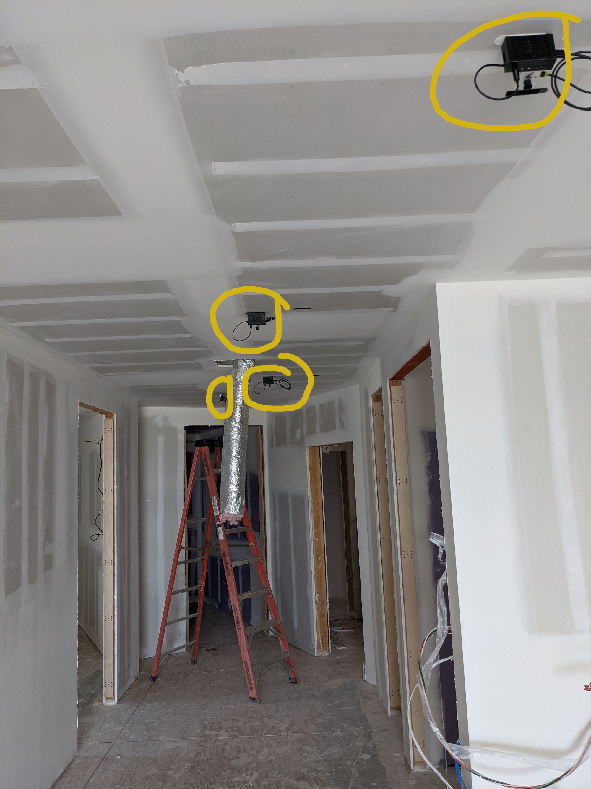
A respectable aruco marker holder was made for antonito to fit in the same mounting holes as the prior VR tracker. Since my 3d printing game was getting stronger, I also added a shroud for the lasers for protection (and to prevent the cameras from getting blinded by the lasers!):
Hand manufactured some camera modules:
And that's all - it surprisingly ALL worked out in the end exactly as we thought it might. Antonito laser-ed 9 apartments over a period of 2 weeks without incident. We lost 3 cameras when they fell from the roof and a few laser modules went bad but otherwise it miraculously all worked out. Here's the robot quietly doing its thing while a few humans stand guard:
I do realize a lot has been skipped in this blog post (specially the software) which I can hopefully cover one day separately. I hope this inspires someone to do better!
As for antonito a lot was learned which would one day hopefully make it into v2!
Many thanks to the amazing team at Social construct (Sam Stowe, Sejun, Tim, Tim, Aarti, Jack, John) for helping with the robot and dealing with us taking valuable space in the office! And to Ben Huh for giving us the opportunity to do something so awesome!